Our Eddy Current Tester hardware
This page describes the design currently being prototyped.
Due to shortages of necessary components, we have been unable to
purchase (or even obtain samples of)
everything we need to assemble this probe prototype.
The manufacturer has expressed regrets for the inconvenience caused.
We hope to continue the development work on our prototype
following the status update that we expect in mid-March.
Mechanical description
Our probe is a small rectangular circuit board with two cables attached
at one corner. The side of the board that will be touching the aircraft
has no components and is covered by a spray-on coating for insulation.
The other side of the board contains a chip in the middle, soldered to
the board and held upright by being glued to a plastic bracket.
This chip is the actual magnetic sensor that detects the aluminum signal.
In a corner of the same side of the board is little collection of components
and two small pushbuttons, which must be pressed in sequence when
instructed by the software.
Electrical description
The magnetic field from our probe can penetrate further into the aluminum
sheet when the frequency is lower, but the measurement also takes longer.
We can see to a depth of 0.1 inches at a frequency of 1 kHz, which ensures an
even illumination of the usual sheet thicknesses we will encounter.
This frequency is where human hearing is especially sensitive
so that ordinary computer sound cards have been designed to work very well.
Therefore, we can operate the probe directly from the sound card,
without needing to incorporate additional expensive acquisition boards.
For thicker multilayers, such as lap joints, we can reduce the frequency;
at 10 Hz, we would be able to illuminate a full inch depth of aluminum.
The sound card codec
AD1819B from Analog Devices,
for example, specifies that it can drive 1 V(rms) into an 800 Ohm load
for frequencies between 20 Hz and 20 kHz.
The microphone input of the AD1819B expects a 10 kOhm source impedance with
a full scale signal between 10 mV(rms) and 1 V(rms) (software selectable).
A planar figure-of-eight coil, as described in the
theory discussion, generates the drive
field using a region of parallel wires. If these wires are created
in the simplest possible way, as traces on a circuit board, the minimum
spacing is about 0.3 mm per layer of board. We will choose the size
of the coil to match the output impedance of the sound card output
so that we deliver 2 mA(rms) of current. As a result, the coil will
generate a field of approximately one Gauss in the body of the aluminum.
At these low frequencies, ordinary pickup coils are very bad at detecting
the magnetic field, emitted by the material in response to our drive field,
and most eddy current systems avoid operating at these low frequencies.
We will use a new kind of magnetic sensor containing materials that have
Amorphous Magneto-Resistance and provide an electrical response
to the magnetic field. This response is the same irrespective of the
frequency, so these sensors are ideal for these audio frequencies.
We plan to use the
HMC1023
(pdf)
from Honeywell's
Solid State Electronics Center.
Those sensors generate a signal of 3 mV/V/Oe. Since the second excitation
signal (from the sound card) is 1 V(rms) and the peak field we expect from
the coil is about 1 Oe, we can expect a maximum input signal of 3 mV(rms).
This is right at the lower limit of what the sound card can accept,
but we can easily boost the signal by a factor of ten using a low cost
audio transformer because the magnetic detector has a low source impedance
of 850 Ohm compared to the sound card's expectation of about 10 kOhm.
Under test, we may observe that the output power available from the
sound card connector is not sufficient. If this is the case,
an external amplifier can be constructed using the Analog Devices
SSM221 chip or similar, providing a thousand times more signal.
Similarly, microphone preamplifier chips can be used if necessary.
The Honeywell sensors require a special circuit that is referred to as
the SetReset. This is used to apply a very short and very
powerful magnetic field to the interior of the detector chip.
This process must be performed whenever the chip is powered up after
having been not used for a while. The details of the circuit are
recommended by the manufacturer. The energy for the magnetic pulse
can be gradually collected from the sound card output by a capacitor/diode
charge pump that is activated by a push-button, and then a separate
button can dump the collected energy rapidly into the detector chip.
Computer Interface Description
Our probe will have two little stereo connectors, at the end of the cable,
which permits it to be directly plugged into the microphone and speaker
jacks that are standard in most computers. Older computers may require
the special addition of a sound card, since these are not always installed.
To evaluate feasibility for future expansion, we plan to implement a
band selective filter that detects a special waveform from the host
computer. This special waveform is used to indicate to the probe
that the software wishes to have a SetReset sequence performed.
In response to this request, the probe could automatically perform
the actions that would otherwise require the user to press buttons.
Alternative Commercial Unit
|
For rather more money than the approach above,
Dr William F. Avrin has developed electronics to perform the same
measurement using Kodak sensor chips instead of Honeywell sensor chips.
Those proprietary electronics generate an output that can be directly
connected to most computer soundcards.
The probe's field coils can be directly driven by such a soundcard.
Thus, this unit can be directly used with the CanDetect software.
Unlike the probe discussed above, which is
still under development and incomplete, Dr Avrin's unit is already
available.
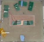
All measurements with CanDetect software, as shown on this website,
used the commercial unit with the probe configured as shown:
|
|
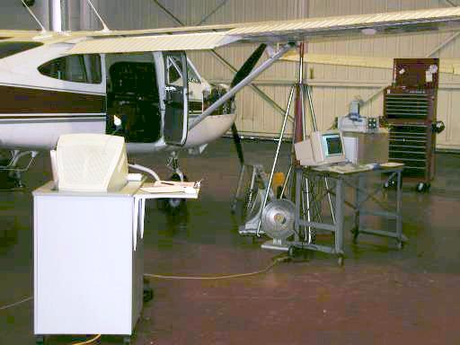
The picture below shows the system on the right,
ready to make measurements on an aircraft in the facilities of
El Cajon Flying Service
at Gillespie airport
(KSEE).
The computer on the left is routinely used by the mechanics to document
and track the work being performed and has nothing to do with this project.
- The Cessna aircraft, currently raised off the ground for
retractable landing gear maintenance;
- A New Internet Computer (NIC) -
computer unit, monitor, keyboard, mouse and cables;
- Dr Avrin's NDE unit, consisting of the electronics and probe; and
- A standard bench power supply instead of a pair of +12V batteries.
The patch cables for connecting the unit to a computer are easily made.
Simply cut an audio extension cord and a BNC coaxial cable in half
and connect each audio half to one BNC half. Solder corresponding
signal wires and grounding shields together and carefully wrap
insulation around the ends to avoid shorts and mechanical damage.
If you're trying to do the same thing and have any questions,
please send me a message
and I'll try to help.